Why Video Splitters and Isolators Matter in GE CT, MRI, and Industrial Monitoring Systems
Why Video Splitters and Isolators Matter in GE CT, MRI, and Industrial Monitoring Systems
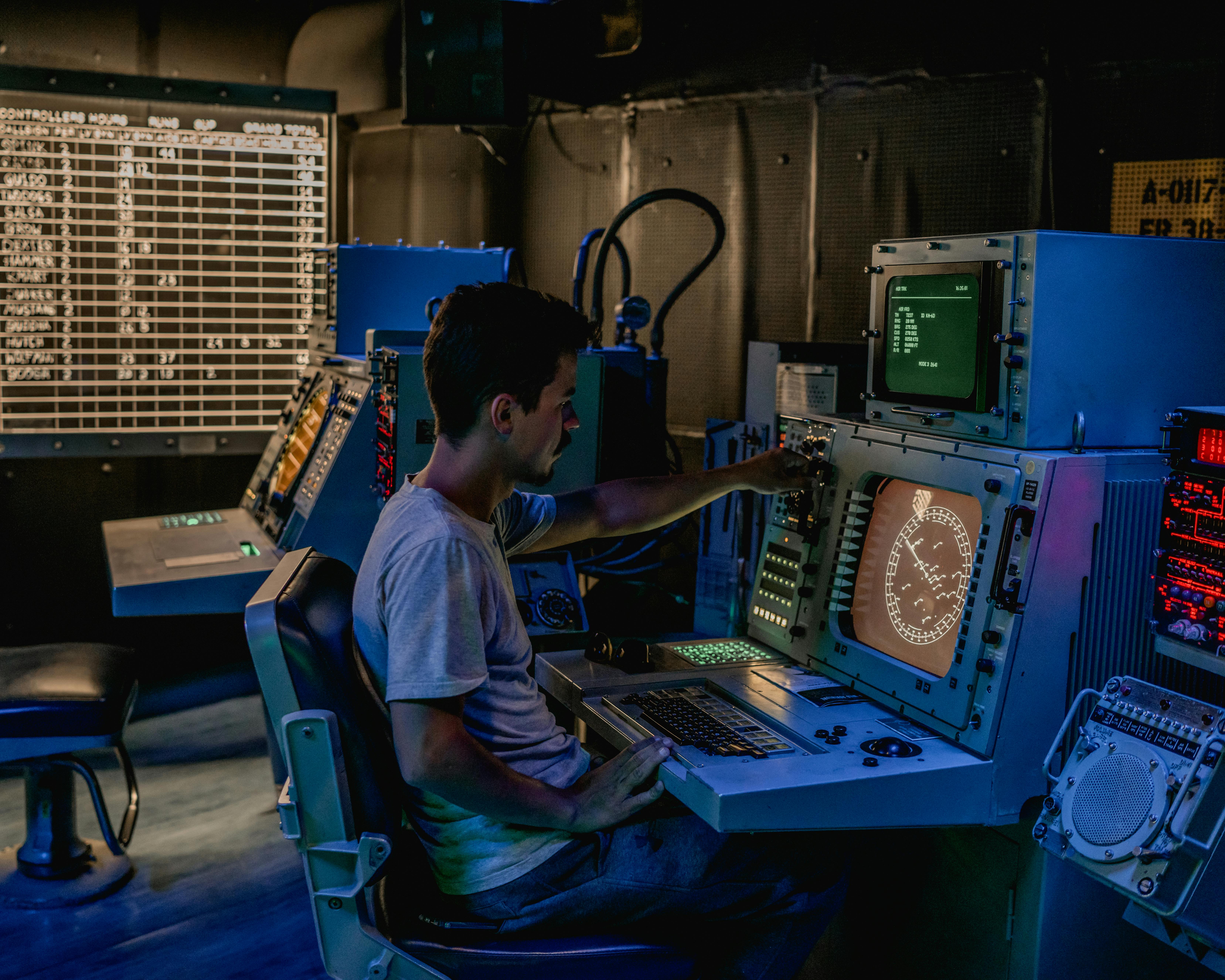
In high-end medical imaging systems such as GE CT and MRI platforms, as well as in industrial monitoring environments, the video splitter or isolator is not just a convenience box. It is a signal-protection component that sits directly in the path between image generation, display distribution, and operational safety. When these units fail or are omitted, the result is often more than a missing screen. Engineers can see ghosting, rolling interference, unstable brightness, damaged interface boards, or in medical environments, unacceptable leakage-risk pathways between different power domains.
Recommended replacement option: Siemens 10790290 Assy MCPPS Output Module
Why This Device Is Necessary
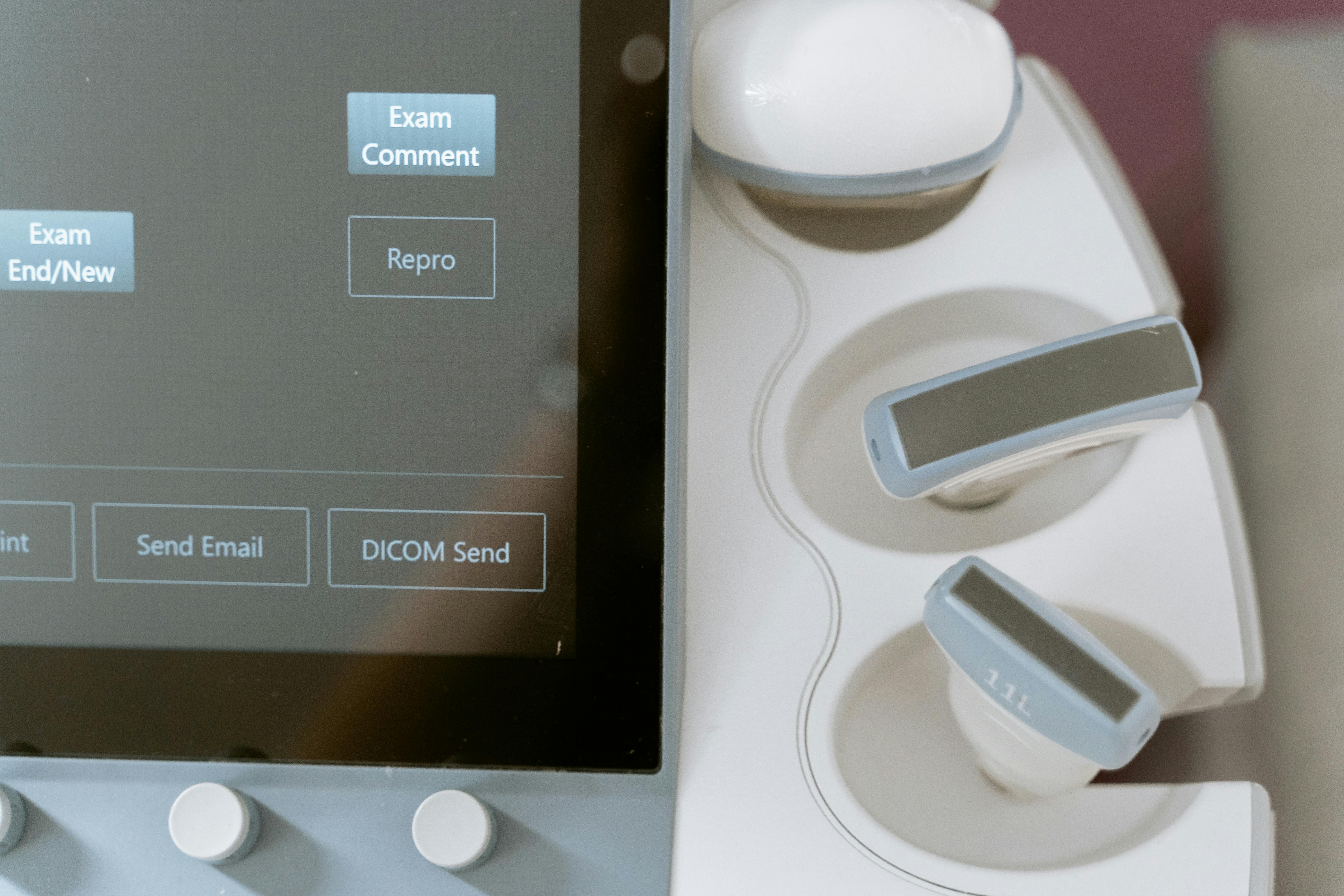
Video signals inside complex equipment are fragile electrical signals. In a noisy environment, simply splitting one output into several destinations without proper conditioning can cause serious problems. A medical imaging console may need to feed an operator monitor, a physician review display, a procedure room screen, and a recording or archive device at the same time. Direct parallel wiring changes impedance, weakens signal quality, and produces visible artifacts. A proper splitter restores each output path to the expected load so the image remains stable and readable.
Isolation is equally important. In healthcare settings, monitors in the operator room and devices near the scan room can sit on different electrical branches. Even small ground potential differences can drive unwanted current through signal cables. That can damage graphics hardware or create leakage concerns that are unacceptable in patient-facing environments. In industrial systems, the same issue appears as rolling bars, flicker, and intermittent instability caused by ground-loop contamination.
The Three Main Jobs of a Video Splitter or Isolator
1. Electrical isolation
The first job is to break direct electrical continuity between systems that should exchange signal but not share fault current paths. This is what protects upstream electronics and helps maintain medical-grade safety boundaries.
2. Multi-output signal distribution
The second job is clean signal duplication. A proper distribution stage does not merely copy a connector; it buffers and amplifies the source so that each output remains correctly driven under a standard impedance load. This is essential when a GE imaging host must serve several displays at once.
3. EMI and RFI suppression
The third job is noise resistance. CT, MRI, industrial drives, and control cabinets all produce harsh electromagnetic conditions. A splitter or isolator with good internal design can reduce high-frequency contamination that would otherwise appear as snow, wave patterns, or unstable image edges.
How These Units Work
Most high-quality splitter/isolation boxes use a combination of buffering, amplification, and isolation methods to preserve the signal.
Buffered signal duplication
When the incoming video signal reaches the device, it first enters a high-impedance buffer stage. That stage behaves like a controlled signal copier. Instead of letting downstream loads pull the source voltage down, it reproduces the signal and compensates for cable losses so each output channel sees a stable drive level.
Ground-loop isolation
This is the heart of the isolator function. Depending on design, the box may rely on optical isolation or transformer-based coupling. Optical isolation converts an electrical signal into light and then reconstructs it on the other side, fully breaking conductive continuity. Transformer coupling transfers the changing component of the signal through electromagnetic induction while blocking unwanted DC bias and direct current paths. Either approach helps stop ground-loop current from riding back through the video line.
Common Failure Symptoms
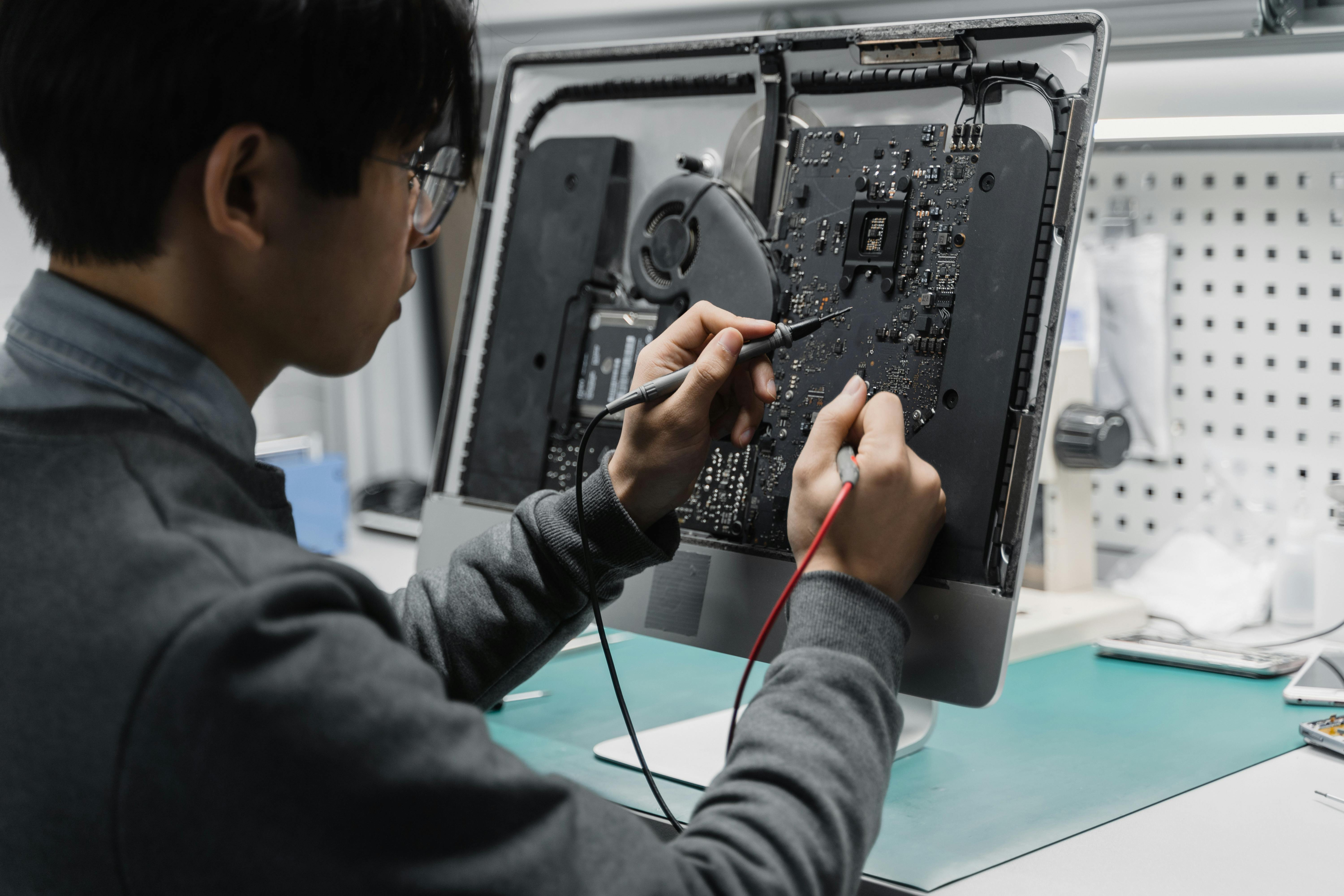
When a video splitter or isolator starts failing, the symptoms usually tell you which part of the unit is in trouble.
- Rolling horizontal bars: often indicate ground-loop interference or degraded isolation performance.
- One output missing or color-shifted: often points to a damaged channel driver or failing output stage.
- Blurry image or trailing edges: often indicate bandwidth limits, impedance mismatch, or poor cable/output matching.
A simple but effective field method is to swap output ports and cables systematically. If the symptom follows the port, the splitter channel is suspect. If it follows the cable or display, the problem is elsewhere.
Engineering Notes for Selection and Installation
Bandwidth matters. Medical imaging displays and industrial HMIs are unforgiving when detail softens or edge definition collapses. As a rule of thumb, the isolation/distribution hardware should provide enough bandwidth headroom to handle the actual signal frequency comfortably, not just barely match the nominal resolution.
Power quality matters too. Engineers often blame the signal path when the real problem is a noisy or unstable adapter powering the splitter. In sensitive systems, low-ripple power supplies and disciplined grounding practice are as important as the box itself.
Final Takeaway
A video splitter or isolator is not an optional accessory in GE imaging or industrial control systems. It is a protective and signal-conditioning layer that preserves image quality, prevents electrical damage, and maintains safe separation between subsystems. When image stability and equipment safety matter, this small box becomes a critical part of the entire system architecture.
Related Articles
The Mystery of the Missing Signal: A Practical Guide to Diagnosing Channel Failures in Industrial Equipment
When a single channel fails in an automation system, the right isolation method can save hours of blind troubleshooting. This guide walks through practical channel-fault diagnosis from signal injection to loopback testing.
Equipment Down? Use This Universal Repair Checklist Before You Pay for Service
Before you call an expensive service line, run this four-step troubleshooting checklist to catch obvious faults, isolate root causes, and reduce preventable downtime.
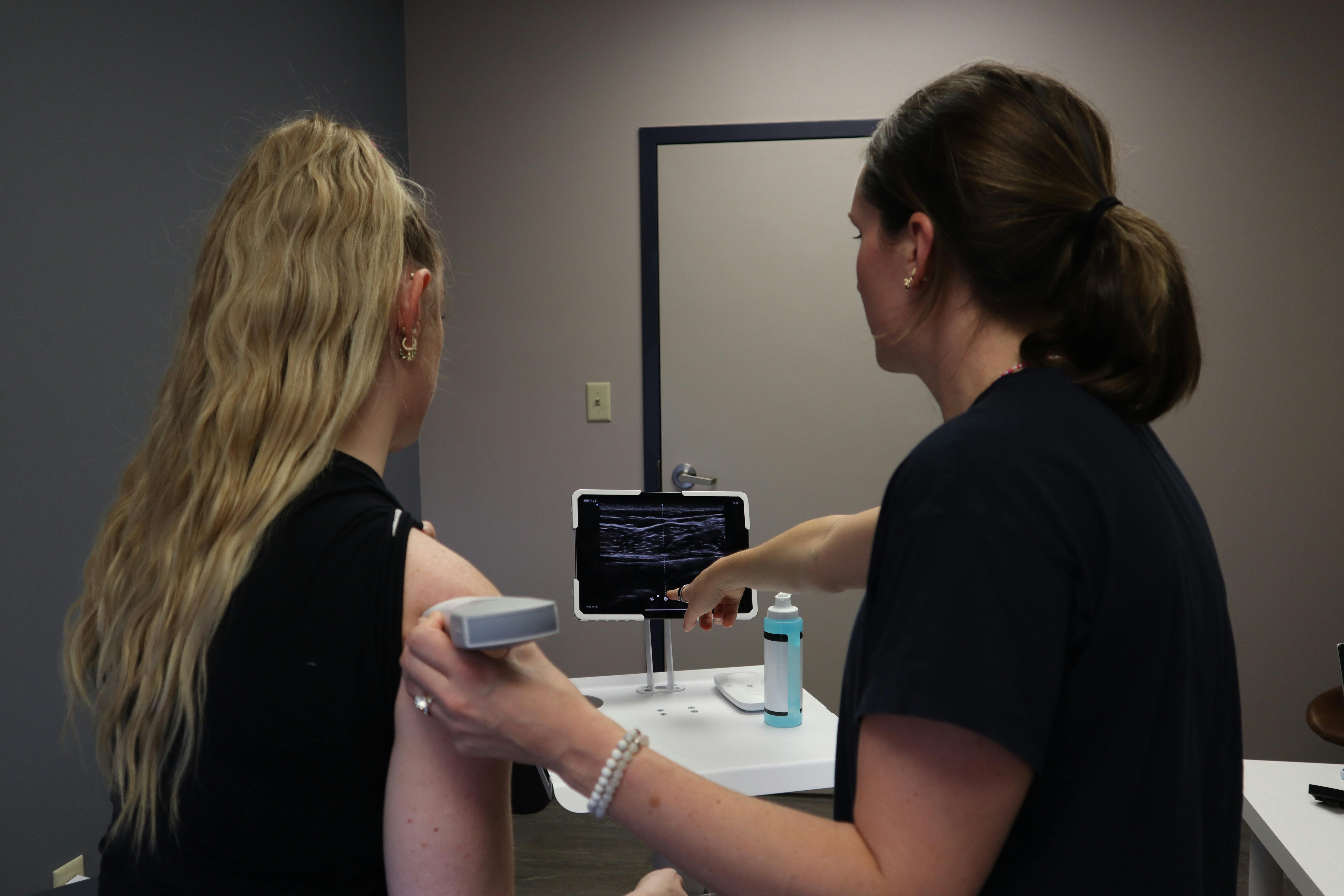
How Predictive Maintenance Reduces Ultrasound System Failures: Insights from a 4-Year Review
A 4-year review of five ultrasound systems found that predictive maintenance reduced repair time and showed a downward trend in breakdowns. Hardware, software, and probe failures each contributed substantially—highlighting the value of structured QA and failure tracking.
