The Mystery of the Missing Signal: A Practical Guide to Diagnosing Channel Failures in Industrial Equipment
The Mystery of the Missing Signal: A Practical Guide to Diagnosing Channel Failures in Industrial Equipment
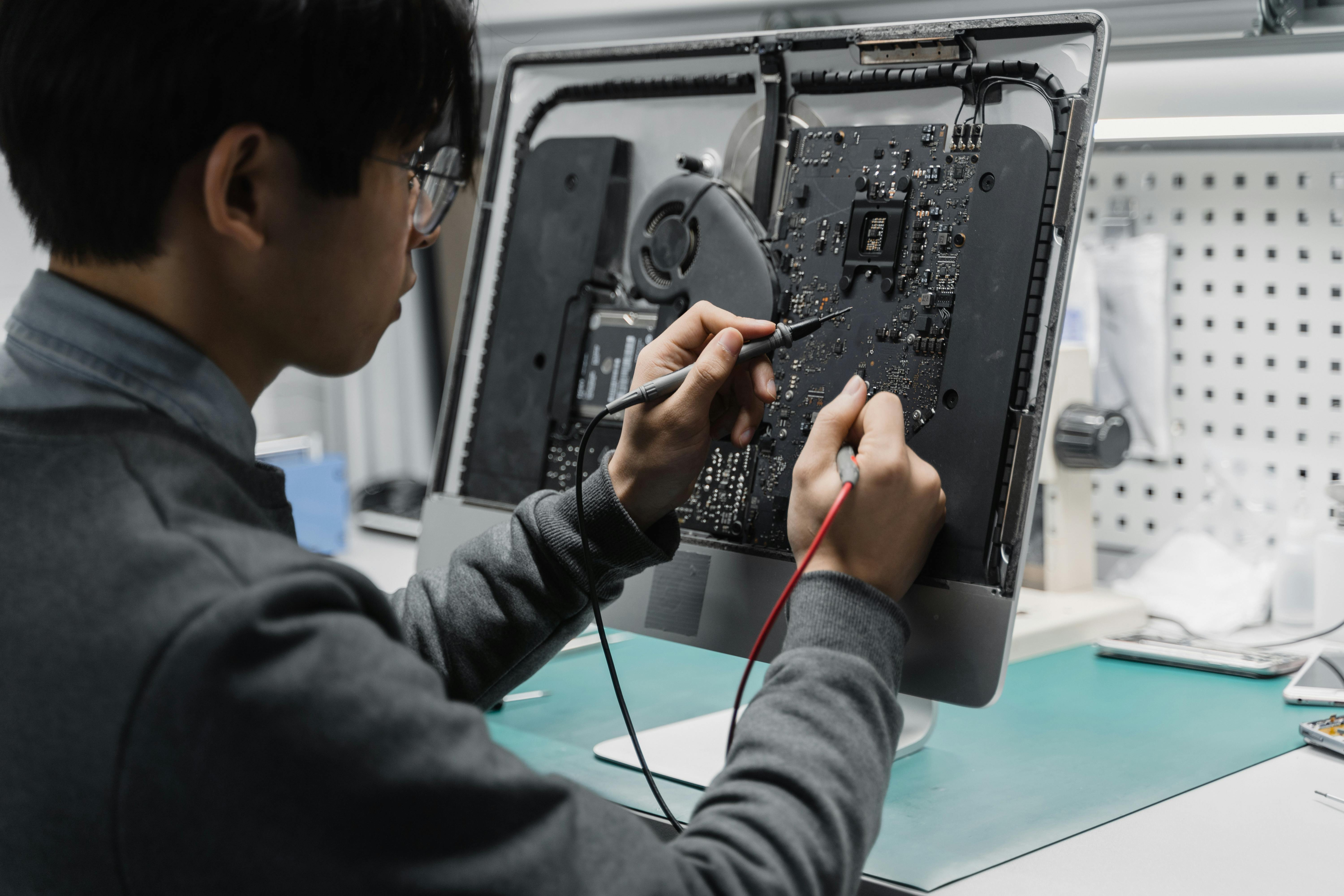
In automation maintenance, the most frustrating failure is often not a total shutdown, but a single channel that suddenly stops behaving. A PLC point loses signal, a sensor value starts drifting, or a communication link cuts in and out without warning. Channel faults are difficult because the system still looks partially alive. The real job is to isolate whether the problem belongs to the field device, the transmission path, or the acquisition side of the control system.
Recommended replacement option: Siemens 10790290 Assy MCPPS Output Module
Start With the Core Logic: Work From Both Ends Toward the Middle
The most effective method for channel troubleshooting is controlled isolation. Instead of guessing, divide the channel into sections and test each part with intention.
1. Signal Injection Simulation
If you suspect a PLC input channel is damaged, do not start by tearing the module apart. Inject a standard test signal such as 4-20 mA or 0-10 V directly at the local input terminal.
- If the system reads normally: the problem is likely in the field wiring or the sensor.
- If the system still shows no response: the input channel itself becomes the primary suspect.
2. Loopback Testing
For communication channels such as RS485 or fiber-based links, loopback testing is one of the fastest ways to narrow the fault domain. Short the transmit side and receive side locally, then check whether the system can send and receive its own data correctly. This often eliminates software configuration doubt in a matter of minutes.
Common Hidden Causes Behind Channel Failures
After years of maintenance work, three causes show up again and again when channels start failing unpredictably:
- Signal drift: often linked to ground loops. Double-ended grounding can create more trouble than grounding itself. Try single-point grounding or install a signal isolator.
- Burned channel hardware: often caused by excessive common-mode voltage. Check whether power cables and signal cables have been routed together and whether shielding has failed.
- Intermittent signal loss: often caused by oxidized terminals or cold joints. These faults are annoying because they can disappear during inspection. Cleaning connectors with IPA and recrimping terminals often solves them.
Field Case: The Disappearing 4-20 mA Signal
A flow meter channel at a chemical plant kept reading zero. The sensor was replaced, but the fault remained. The next step was not guessing, but measurement.
- Voltage check: the input side showed only about 1 V, far below the expected loop supply level.
- Load isolation: after disconnecting the signal wiring, the module output returned close to normal.
- Root cause: the channel still worked without load, but collapsed under load. Inspection later showed that a current-limiting resistor had drifted after long-term overheating.
Replacing the damaged resistor brought the channel back to life and saved the site from replacing the entire module.
How to Prevent Future Channel Failures
- Design spare capacity: reserve 15% to 20% spare channels during system design. When a point fails, you can remap logic to a spare point and restore production first.
- Add surge protection: outdoor channels should have proper signal surge protection. Sensitive control boards should not be left exposed to transient energy.
- Avoid live hot-swaps in harsh environments: even if a module claims hot-swap support, wet or dusty environments increase arc risk and channel damage.
Final Thought
Channel repair is not brute-force work. It is disciplined thinking. If you stay calm and follow a closed loop of disconnect, simulate, compare, and confirm, most channel failures become traceable instead of mysterious.
Related Articles

Why Video Splitters and Isolators Matter in GE CT, MRI, and Industrial Monitoring Systems
Video splitters and isolators do far more than duplicate a display feed. In medical imaging and industrial monitoring systems, they protect equipment, preserve image integrity, and prevent dangerous ground-loop problems.
Equipment Down? Use This Universal Repair Checklist Before You Pay for Service
Before you call an expensive service line, run this four-step troubleshooting checklist to catch obvious faults, isolate root causes, and reduce preventable downtime.

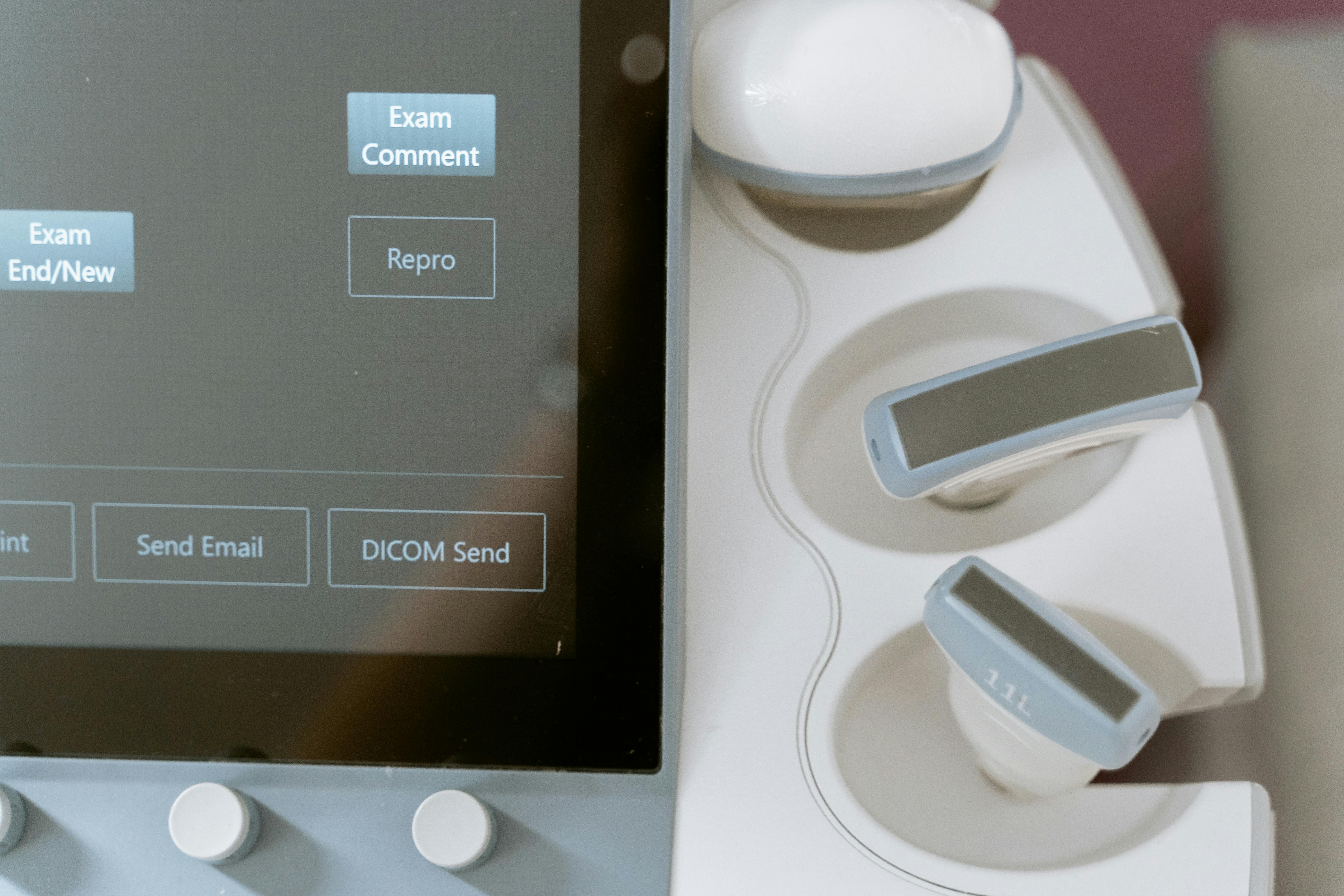
How Predictive Maintenance Reduces Ultrasound System Failures: Insights from a 4-Year Review
A 4-year review of five ultrasound systems found that predictive maintenance reduced repair time and showed a downward trend in breakdowns. Hardware, software, and probe failures each contributed substantially—highlighting the value of structured QA and failure tracking.
