In-Depth Analysis: Common Causes of Power Supply Failures in Medical Ultrasound Systems
In the realm of medical imaging, the ultrasound system is a cornerstone of diagnostic capability. While the transducer probes and image processing engines often garner the most attention, the Power Supply Unit (PSU) acts as the critical physiological heart of the machine. It is responsible for converting unstable AC mains electricity into precise, clean DC voltages required by sensitive analog and digital components.
However, power supply failures remain one of the most frequent causes of equipment downtime in clinical settings. A failure in the PSU does not merely prevent the system from powering on; it can introduce noise artifacts into diagnostic images, damage expensive frontend boards, or pose safety risks to patients. Understanding the root causes of these failures is essential for biomedical engineers and hospital technicians.
This article provides a professional analysis of the common reasons behind ultrasound power supply damage. We will examine the technical mechanisms of failure and review specific examples found in widely used industry equipment.
The Architecture of Vulnerability: Why PSUs Fail
Modern ultrasound machines predominantly utilize Switch-Mode Power Supplies (SMPS) due to their efficiency and compact size compared to linear supplies. Despite their advantages, SMPS units operate under high stress, managing high currents and rapid switching frequencies. This operational environment makes them susceptible to a variety of internal and external stressors.
1. Thermal Stress and Component Aging
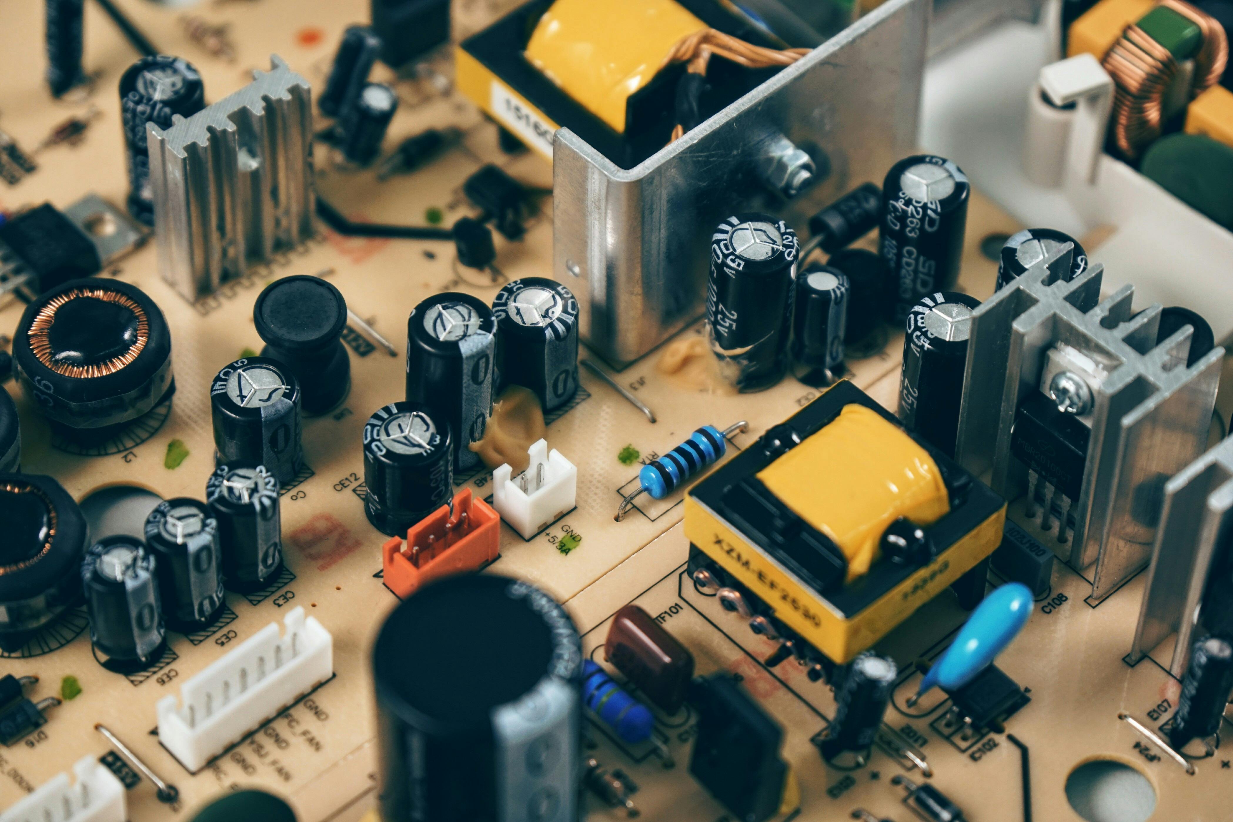
Heat is the primary enemy of electronic reliability. Ultrasound machines are often compact, with densely packed components that restrict airflow. Over time, the electrolytic capacitors used for filtering in the PSU begin to degrade.
As the internal electrolyte evaporates due to sustained heat, the Equivalent Series Resistance (ESR) of the capacitor increases. This leads to ripple voltages that exceed the tolerance of downstream components. Eventually, the capacitor may bulge, leak, or fail open, causing the power supply to shut down to protect itself.
2. Environmental Contamination
Clinical environments are generally clean, but ultrasound machines often rely on active cooling fans that draw in air continuously. Over months or years, dust and lint accumulate on the internal components of the power supply.
This dust layer acts as a thermal insulator, preventing heat dissipation from critical power transistors (MOSFETs) and diodes. In humid environments, this dust can also become conductive, leading to short circuits across high-voltage traces on the Printed Circuit Board (PCB).
3. Electrical Grid Instability
Medical facilities usually have robust power infrastructure, but localized surges or brownouts can still occur. Ultrasound PSUs are designed to handle a specific range of input voltages.
If the input voltage fluctuates rapidly or spikes beyond the breakdown voltage of the metal-oxide varistors (MOVs) used for protection, the input stage of the PSU can be destroyed. This is particularly common in mobile ultrasound units that are frequently plugged into different outlets throughout a hospital.
Specific Case Studies of Common Ultrasound Power Failures
To illustrate these theoretical failure modes, it is valuable to examine specific scenarios often encountered by service engineers. Different manufacturers utilize unique power architectures, leading to characteristic fault patterns.
Case Study 1: Philips IU22 and IE33 AC/DC Power Module
The Philips IU22 and IE33 systems are workhorses in the industry, but they are notorious for power supply issues related to their AC/DC tray. A common symptom presents as the system failing to boot, often accompanied by blinking LEDs on the control panel or no reaction at all.
The Technical Fault: The failure frequently originates in the 300V rectification stage. The large electrolytic capacitors responsible for the DC bus often degrade. Furthermore, the soft-start circuitry, which limits inrush current, is prone to failure.
Consequences: When these components fail, the system detects an instability in the main voltage rails. The motherboard logic prevents the boot sequence to avoid damaging the expensive UMB (Unified Motherboard). Technicians often observe that the "AC Present" light at the back remains off or flickers.
Case Study 2: GE Voluson and Logiq Series High-Voltage (HV) Rails
GE Healthcare’s ultrasound systems, such as the Voluson E8 or Logiq E9, utilize complex power distribution systems. A distinct failure mode in these units involves the High Voltage (HV) power supply, which is specifically dedicated to driving the transducer elements.
The Technical Fault: The HV power supply must generate variable high voltages (e.g., +/- 10V to +/- 90V) to control the acoustic output power. Failures here are often linked to the regulation feedback loops or the failure of output transistors.
Consequences: Unlike a total system blackout, an HV supply failure often results in specific imaging artifacts. Users may report "shadowing," dark vertical bands in the image, or the inability to use certain high-power probes. In severe cases, the system will display a proprietary error code indicating that the HV rail is out of tolerance and will disable scanning functions.
Case Study 3: Portable Ultrasound Battery Charging Circuits
Portable units, such as those from Mindray (e.g., M7, M9) or Sonosite, face a unique set of power challenges. These devices switch frequently between AC adapters and internal lithium-ion batteries.
The Technical Fault: The failure often lies in the power management ICs responsible for switching the power source. Frequent plugging and unplugging wear out the DC input jack, causing intermittent contact and arcing.
Consequences: The device may work on battery but fail to charge, or shut down immediately when the AC adapter is removed. This is often misdiagnosed as a bad battery, when in reality, the charging circuit on the main power board has sustained damage from voltage spikes or physical stress.
Diagnostic Approaches and Maintenance
Diagnosing power supply failures requires a systematic approach. Biomedical engineers should begin with a visual inspection, looking for bulging capacitors, charred components, or signs of arcing. However, visual signs are not always present.
Load Testing: A PSU may output the correct voltage when disconnected (no load) but fail immediately when the ultrasound machine attempts to draw current. Therefore, testing voltage rails while the system is under load is crucial for accurate diagnosis.
Ripple Measurement: Using an oscilloscope to measure the AC ripple on DC rails can reveal aging capacitors before they cause a catastrophic failure. Excessive noise on the 5V or 3.3V digital rails is a leading cause of intermittent software crashes and freezing.
Conclusion
The power supply unit is a sophisticated component that dictates the reliability and longevity of medical ultrasound equipment. Failures are rarely spontaneous; they are typically the result of cumulative thermal stress, component aging, or environmental factors.
By understanding the specific failure modes of systems like the Philips IU22 or GE Voluson series, technical personnel can expedite repairs and reduce downtime. Furthermore, implementing a strict preventive maintenance schedule that includes dust removal and power conditioning can significantly extend the lifespan of these vital medical devices.
Related Articles

Common Technical Faults in Medical Ultrasound Systems: A Comprehensive Analysis
An in-depth professional analysis of the most frequent hardware and software failures in medical ultrasound machines, ranging from transducer damage to power supply instability and user interface malfunctions.
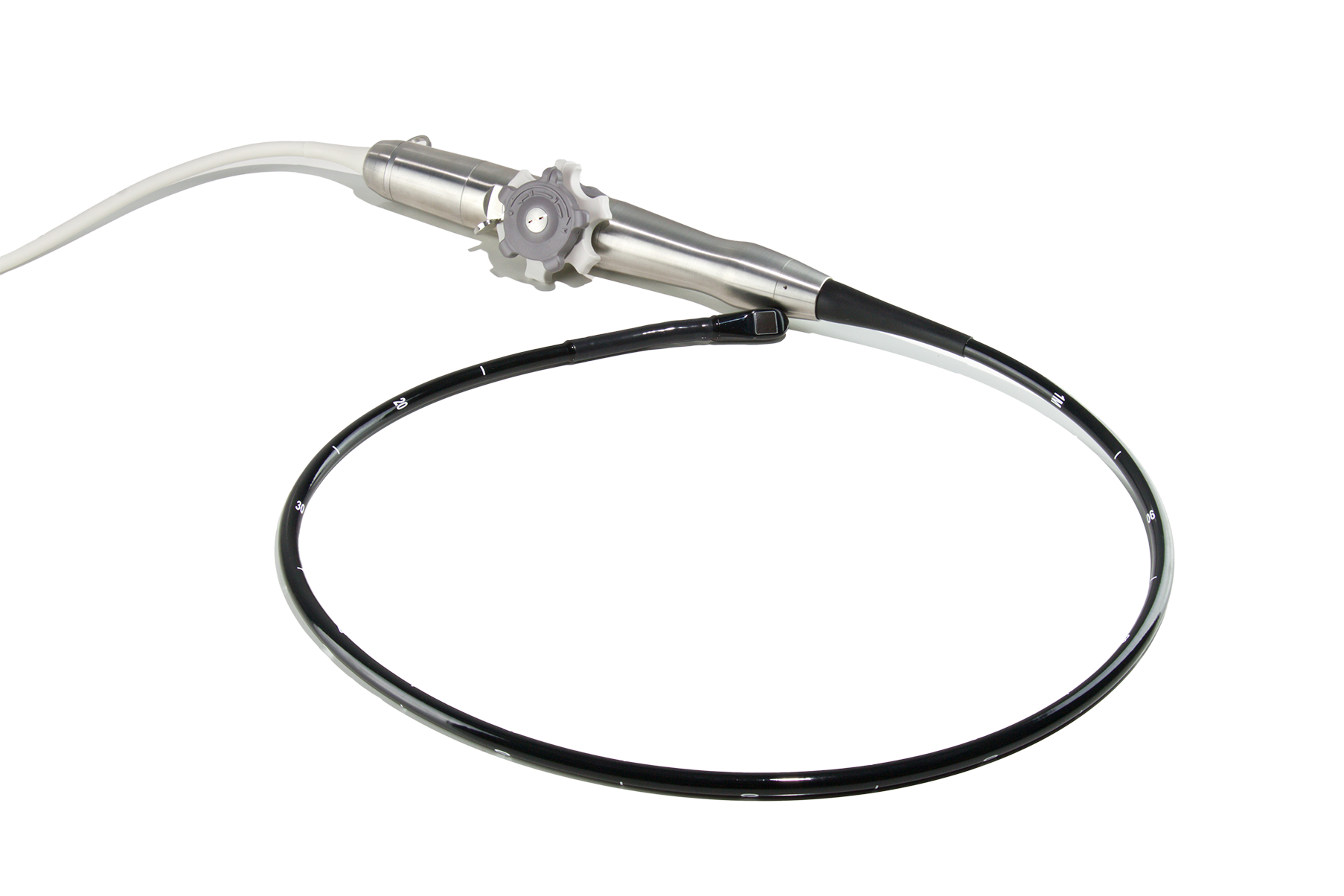
Освоение ЧПЭхо-датчика Philips X7-2t: распространенные неисправности, диагностика и решения по ремонту
Полное руководство по поиску и устранению неисправностей и обслуживанию усовершенствованного ЧПЭхо-датчика Philips X7-2t с технологией xMatrix, охватывающее механические поломки, электронную диагностику и протоколы профессионального ремонта.
