The Critical Link: How Ultrasound Transducer Design Defines Beamforming Quality
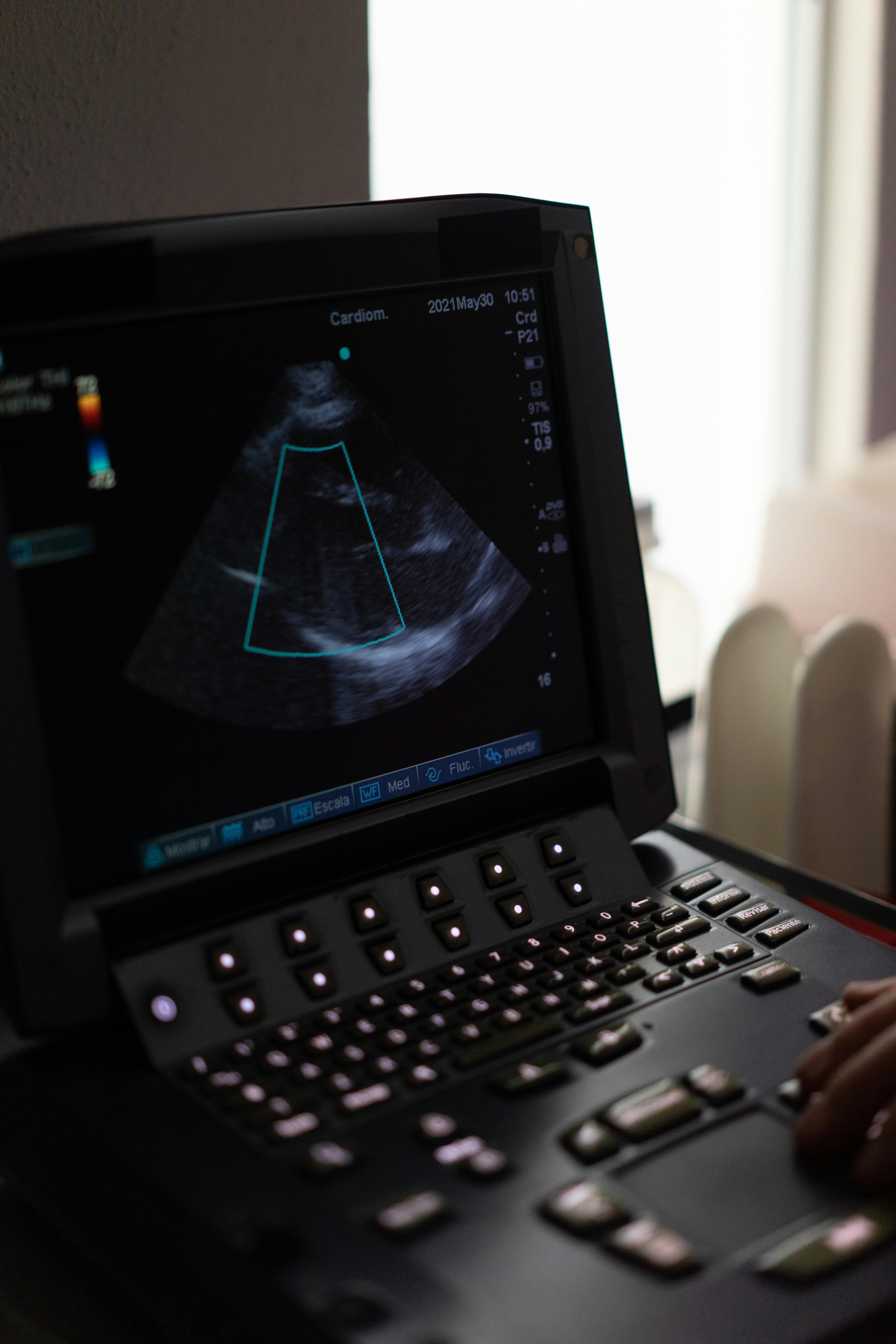
In the world of medical diagnostics, the ultrasound machine is often viewed as a singular unit of advanced technology. However, the clarity of the final image relies heavily on a specific component: the transducer, or probe. While the backend console handles the heavy computational lifting of beamforming, it is the physical design of the probe that sets the fundamental limits for image quality.
The relationship between transducer architecture and beamforming is symbiotic yet strictly hierarchical. Even the most sophisticated digital beamformer cannot fully correct for a poorly designed acoustic stack or improper element configuration. Understanding this connection requires a deep dive into the physics of sound and the engineering of sensor arrays.
The Acoustic Stack: The Foundation of Signal Fidelity
At the heart of every ultrasound probe lies the acoustic stack. This multi-layered structure is responsible for converting electrical energy into sound waves and vice versa. The quality of the raw signal generated here dictates the potential of the subsequent beamforming process.
Piezoelectric Materials and Bandwidth
The core component is the piezoelectric crystal, which vibrates to produce sound. Modern probes have shifted from traditional PZT ceramics to single-crystal materials to enhance efficiency. This material choice directly impacts the bandwidth of the transducer.
A wider bandwidth allows the beamformer to utilize short-pulse excitation. Shorter pulses translate immediately to superior axial resolution, allowing the system to distinguish between structures that are positioned close together along the beam's path. If the transducer design limits bandwidth, the beamformer is forced to use longer pulses, blurring fine details regardless of the processing power applied later.
Damping and Matching Layers
Behind the crystal lies the backing block, or damping material. Its primary role is to stop the crystal from ringing excessively after excitation. Heavy damping creates a short spatial pulse length, which is critical for high-resolution imaging.
Conversely, the matching layers on the face of the probe facilitate the transfer of acoustic energy into the patient. Without precision-engineered matching layers, a significant portion of the signal is reflected back at the skin surface. This loss of energy results in a poor Signal-to-Noise Ratio (SNR), giving the beamformer a weak, grainy signal that is difficult to reconstruct into a clean image.
Element Pitch and Grating Lobes
When moving from the materials to the arrangement of the array, the geometry becomes the dominant factor in beamforming quality. The spacing between individual piezoelectric elements, known as the "pitch," is a critical design parameter.
Beamforming relies on constructive and destructive interference to steer and focus the ultrasound beam. However, if the elements are spaced too far apart relative to the wavelength of the sound, a phenomenon known as grating lobes occurs.
- Grating Lobes: These are secondary beams of energy that shoot off in unintended directions.
- Artifact Generation: If these lobes strike a strong reflector, the machine creates a ghost image, placing the structure in the wrong location.
- Design Constraint: To eliminate grating lobes, the element pitch must generally be less than half the wavelength of the sound frequency used.
Therefore, a high-frequency probe designed for superficial imaging requires an incredibly fine pitch. This increases the manufacturing complexity and the number of channels the beamformer must process. If the design compromises on pitch to save cost, the beamformer's ability to suppress artifacts is physically compromised.
Aperture Size and Lateral Resolution
The width of the active transducer array, or the aperture, governs the lateral resolution of the image. Lateral resolution is the ability to distinguish two points located side-by-side at the same depth. Physics dictates that a wider aperture allows for a tighter focus at greater depths.
Beamforming algorithms use a technique called dynamic aperture, where the system activates more elements as the signal returns from deeper tissues. However, the beamformer is limited by the physical width of the probe.
For example, a small footprint phased array probe, often used in cardiology to fit between ribs, has a physically small aperture. Consequently, the lateral resolution at significant depths will naturally degrade compared to a large linear array. The probe design establishes a "diffraction limit" that no amount of digital processing can overcome.
Elevation Focus and Slice Thickness
Standard 1D array transducers have a limitation that significantly affects image quality: slice thickness. While the beamformer can dynamically focus the beam electronically in the imaging plane, the focus in the elevation plane (the thickness of the slice) is usually fixed by a mechanical lens.
This creates a fixed focal point. Structures outside this focal zone may appear thicker or suffer from partial volume averaging artifacts. This is where advanced transducer designs, such as 1.5D or 2D matrix arrays, come into play.
By segmenting elements in the elevation direction, the probe design allows the beamformer to exercise electronic control over slice thickness. This capability significantly improves contrast resolution and reduces clutter, demonstrating how adding complexity to the hardware design unlocks new capabilities for the beamforming software.
Conclusion
The relationship between ultrasound probe design and beamforming quality is one of potential and realization. The transducer design—encompassing material selection, element pitch, and aperture geometry—defines the physical constraints of the acoustic signal. The beamformer then operates within these constraints to construct the best possible image.
High-quality imaging is impossible without a probe that delivers high bandwidth, suppresses grating lobes, and maximizes signal transfer. As medical imaging demands higher precision, the engineering of the transducer remains the critical first step in the imaging chain.
Related Articles

Why Minor Console Delay Can Reveal a Broader Ultrasound Control Failure Path
Small but repeatable control inconsistency can be the earliest visible sign of a deeper console-side signal, board, or interface failure path.

Why Minor Console Delay Can Be an Early Sign of Deeper Ultrasound Control Failure
Small control delays often show up before a larger console-side failure becomes obvious, especially when repeated use starts exposing signal or board instability.
Why Early Control Drift Can Reveal a Deeper Console Failure Path in Ultrasound Systems
Small but repeatable control inconsistency can be the earliest visible sign of a deeper console-side signal, board, or interface failure path.
