Why Repeated Soft-Control Inconsistency Can Expose Console-Interface Weakness Before Full Failure
Last updated: August 4, 2026
⚠️ Scope and Disclaimer: This article is written for clinical engineering managers and equipment procurement decision-makers evaluating probe interface component replacement for ultrasound systems. It does not constitute repair instructions. Installation should be performed by qualified biomedical engineers following the OEM service manual and electrical safety protocols. Pricing ranges cited are industry estimates and vary by region, supplier, and unit condition. GE is a trademark of General Electric Company; geprobe is an independent third-party supplier and is not affiliated with or endorsed by GE.
A replacement ultrasound probe costs $5,000–15,000. A probe interface board costs $200–600. On a purchase order, they sit an order of magnitude apart. In symptom presentation, they can look identical: image quality that comes and goes, gain that needs to be pushed higher every month, a port that occasionally refuses to recognize the probe.
Most departments, faced with these symptoms, reach for the same reflex: "The probe's getting old—put in a purchase request for a replacement." That instinct is right some of the time. But a meaningful fraction of the time—based on what we've observed across years of ultrasound parts supply, roughly 20–30% of "probe failure" procurements—the real fault isn't inside the probe. It's behind the probe socket: the connector board, the interface relay, the probe selector board, the port extension. An $8,000 probe gets swapped in. The symptoms don't resolve. And that's when you discover a $300 relay with oxidized contacts was the actual problem. That's not diagnosis. That's using the procurement budget as a diagnostic tool.
This article explains how to separate probe-body faults from probe-interface faults with three zero-cost tests—before the purchase order goes through. And when the fault does land in the interface layer, how to navigate GE's probe interface component category and buy exactly the board you need.
What follows covers the full decision chain:
- Section 1: Three interface-layer symptoms that reliably get misdiagnosed as "the probe is dying"—and why the price difference between the two diagnoses is a full order of magnitude
- Section 2: The physics of the probe signal path—every connector, relay, selector, and cable segment between the transducer crystal and the beamformer, and how each one degrades
- Section 3: A three-step differential diagnosis—port cross-validation, connector visual inspection, and multi-probe symptom cross-referencing—that takes 15 minutes and can save $5,000–15,000
- Section 4: GE probe interface component procurement—a three-tier architecture, a symptom-to-component decision tree, and a 78-product category overview
- Section 5: GE probe interface procurement checklist—five pre-order questions tailored to microvolt-level analog signal paths, and acceptance testing built around port cross-validation under thermal stabilization
Probe Image Quality Comes and Goes — Operators Blame the Probe, but the Fault May Sit Behind the Socket It Plugs Into
A probe doesn't degrade from "perfect image" to "unacceptable image" along a smooth line. There's a long gray zone in between—today the image looks fine, tomorrow the gain needs two extra notches, the day after a dark band appears at one scan angle, then disappears again. The operator's description is usually vague: "This probe's not performing like it used to" or "the image doesn't feel as clean."
Nobody writes a purchase-justification memo for "the image doesn't feel as clean." But when the vague description finally crystallizes into a procurement request, it typically carries one line: "Replace probe ×1."
Three Interface-Layer Symptoms That Reliably Get Misread as Probe Failure
Each of the following three presentations triggers the same procurement reflex—"buy a new probe." Each has a substantial probability of not being a probe problem at all.
Symptom One: Intermittent probe non-recognition. The system boots up and displays "probe not detected" or shows a grayed-out probe icon. Reboot—recognized. Next morning, cold boot—not recognized again. The operator says "this probe has a bad connection." They might be half right. It is a bad connection—but not at the probe plug end. It's oxidation on the system-side connector board pins, or a probe selector board whose logic-level output is hovering at the decision threshold. Plug a brand-new probe into the same port—same intermittent non-recognition.
Symptom Two: Gain creeps higher month over month; graininess builds. This is not exclusive to crystal sensitivity decay. The probe's echo signal travels from the piezoelectric elements to the beamformer through connectors → ribbon cables → relays → selectors → more ribbon cables (depending on platform architecture). Every oxidized contact surface and every buffer chip with degraded drive strength along that chain injects broadband noise into a microvolt-level signal. The beamformer cannot distinguish "signal attenuation" from "noise superposition"—it processes both the same way. Signal-to-noise ratio margin shrinks from the factory 10–12 dB to 2–3 dB. Gain compensation pulls the signal up—but noise comes up with it. That's where the grain comes from. Swap in a new probe—SNR margin does temporarily recover—but if the noise injection point is in the interface layer, the new probe's signal still passes through it. Six months later, you're back where you started.
Symptom Three: A fixed dark band in the image that doesn't move when you change the scan angle. A 128-element linear probe routes element signals through specific pin groups on the connector. If a handful of connector pins have contact resistance far higher than the rest—selective attenuation on those element channels—the corresponding image zone darkens. Change the scan angle, and the dark band stays in the same place in the image (because it follows the physical element group, not the scan-line direction). First instinct: "The probe crystals are failing." But if it's selective connector-pin oxidation, the same dark band will appear on any probe plugged into that same port. Port cross-validation rules this out in minutes.
$5,000–15,000 vs. $200–600 — The Diagnostic Fork Before the Purchase Order
| Procurement Path | Cost | Pre-Purchase Diagnostic Time | Cost of Being Wrong |
|---|---|---|---|
| Replace the probe directly | $5,000–15,000 | Zero (order based on operator description) | If the fault is in the interface layer—$5,000–15,000 wasted; symptoms persist or return within months |
| Port cross-validation first → confirm interface layer → replace interface board | $200–600 | 15 minutes | If the fault is in the probe and the interface is healthy—no money wasted, just 15 minutes spent. Then proceed with normal probe procurement |
| No diagnosis; replace interface board first → if that doesn't fix it, replace the probe | $200–600 + $5,000–15,000 | Two waiting periods (interface board arrives + probe arrives) | If the fault is in the probe—$200–600 wasted plus extra days of downtime |
💡 Expert Insight: Port cross-validation is the most undervalued 15 minutes in pre-procurement diagnostics. Plug the suspected probe into ports 1, 2, and 3 sequentially. Run the same image-quality test on each. Symptoms follow the probe → probe-body fault; buy a probe. Symptoms stay locked to one port → interface-layer fault; buy an interface board. Symptoms are identical across all ports → simultaneous multi-probe aging is extremely unlikely (unless all probes were purchased and put into service on the same day)—more likely a beamformer-backend or system power-rail issue. Fifteen minutes. Potential value: $5,000–15,000.
"We Swapped the Probe and It's Still the Same" — The Most Expensive Diagnostic Conclusion
This sentence appears in clinical engineering procurement records more often than you might think. The old probe may genuinely have aged—the image may genuinely be worse than it was three years ago. But what tipped the image from "acceptable" to "unacceptable" was the noise injection from the interface layer. The new probe arrived with fresh crystal sensitivity and higher starting SNR—enough extra margin to temporarily compensate for the interface noise. The image looked better. But it didn't look like a new machine. The operator assumed "new probes need a break-in period" or "that's just how this probe model performs." Neither was true. The new probe's extra SNR headroom was masking the interface noise. As the new probe's crystals began their own natural aging curve, the headroom eroded. The image returned to baseline—and that's when someone finally ran a port cross-validation and found the interface fault. From first complaint to definitive diagnosis: six months, two probes, cumulative machine downtime. The unit cost of that diagnostic conclusion: roughly $8,000.
The Physics of the Probe Signal Path — From Transducer Crystal to Beamformer, Every Stop on the Chain
A probe transmits ultrasound, receives echoes, converts acoustic energy to electrical signals—but those microvolt-level echo signals pass through multiple hardware gates before reaching the beamformer. Every gate is a potential noise-injection point or signal-attenuation point.
Probe Connector Board Contact Resistance Creep — Every Insertion Cycle Consumes the Gold Fingers
A probe connector is not a USB port. It doesn't carry digital data packets. It carries 64–256 channels of microvolt-level analog echo signals, and every one of those channels is far more sensitive to contact resistance than any digital signal. A digital signal only needs to distinguish 0 from 1—contact resistance can quintuple with zero functional impact. An analog echo signal has no such tolerance. Contact resistance that quintuples means that element channel's signal is attenuated by 5–8 dB. The corresponding zone in the image goes dark.
The gold-finger contact surfaces inside the connector experience micron-scale friction with every insertion cycle. A typical ultrasound department swaps probes 2–4 times per day (abdominal exam finished → swap to linear → linear finished → swap to phased array). That's roughly 1,000 insertion cycles per year. Over three years: 3,000 cycles. Under high-magnification inspection after 3,000 cycles, gold-finger plating shows clear striation bands. In some areas, the gold layer has worn through entirely, exposing the nickel or copper underlayer. Contact resistance has climbed from the factory 20–50 mΩ to 200–500 mΩ—and the increase is concentrated on the specific pins that see the highest insertion-cycle count.
This is why port 1 (most frequently used) shows worse image degradation than ports 2 and 3 (occasional use). Not because the system favors port 2. Because port 1's connector has seen 3,000 insertions while port 2 has seen perhaps 500.
Probe Interface Relay Contact Oxidation — the Weakest Link in Multi-Probe Switching Systems
High-end GE platforms (Logiq E9/E10, Vivid E95, Voluson E8/E10, and others) support 3–4 probes connected simultaneously with one-touch software switching. That switching action is not virtual. Inside the system, a physical relay assembly (Probe Interface Relay Assembly or Probe Switch Relay) performs a mechanical contact break-make cycle every time you switch probes.
Mechanical relay contacts have two natural enemies: micro-arcing and oxidation.
Every time the contacts open, the energy stored in the回路 inductance produces a tiny arc across the contact gap—microjoule-level energy, invisible to the naked eye. The arc heat deposits a nanometer-scale layer of carbonized material on the contact surface. After 10,000 switching cycles (a machine averaging 10 probe switches per day reaches this in about three years), carbonized deposits push contact resistance from <50 mΩ to 200–500 mΩ. Simultaneously, contacts sitting open are exposed to ambient air—silver-alloy or gold-plated surfaces oxidize slowly over time.
The two mechanisms combine to produce a distinctive symptom pattern: port 1 (high-frequency use) relay contacts → image noise 3–5 dB higher than port 2 (low-frequency use). The operator doesn't know a physical relay is performing mechanical work every time they click "switch probe." They just know that "the linear probe looks cleaner on port 2 than port 1." They conclude: "Port 1 might have an issue. I'll just use port 2 from now on." That workaround holds for a while—until port 2's relay begins its own degradation curve.
⚠️ Watch Out for the Software-Switching Illusion: One-touch probe switching on the operator panel makes the action feel wear-free ("I'm just clicking a button"). But behind that button, a physical relay is performing mechanical work—each click consumes one cycle of contact life. This perception gap is the root reason relay degradation is systematically diagnosed late. No operator logs a service ticket for "I switched probes 10,000 times and now it feels slightly slower." But that's exactly what happened.
Probe Selector Board Logic-Level Wander — Why Port 1 Works While Port 2 Occasionally Won't Recognize the Probe
The multiplexer/demultiplexer chipset on the Probe Selector Board (PSB) is responsible for connecting the active probe port to the beamformer front end based on system commands. These chips are active continuously—as long as the system is powered on, they maintain the current port selection state.
After hundreds of millions of logic transitions, the output-stage PMOS pull-up and NMOS pull-down transistors in CMOS chips experience threshold voltage drift—pull-up weakens, pull-down weakens. The output logic-high level decays from the factory 3.3V—3.2V → 3.0V → 2.7V → 2.3V. When the high level approaches the next-stage chip's input-high threshold (VIH, typically around 2.0V), the receiving end can no longer reliably determine "is this a 1 or a 0?" The port-select signal becomes indeterminate—the selector output oscillates between port 1 and port 2 at high frequency. The system sees "probe not present"—because with the port selection unstable, the probe ID ROM readback fails checksum.
What the operator experiences: "The probe occasionally isn't recognized. A reboot fixes it." The reboot cold-resets the selector chip and temporarily restores logic levels—but the chip's threshold drift hasn't changed. Three months later, "occasionally" becomes "frequently," and "a reboot fixes it" becomes "it took three reboots."
Ribbon Cables and Port Extension Boards — the Shared Degradation Curve on Both Sides of the Connector
The final physical segments of the probe signal path are the internal ribbon cables and the port extension board (Probe Port Extension). Copper-foil flex fatigue in ribbon cables (same mechanism detailed in the previous article on repeated-input drift) and connector oxidation on the port extension board both inject noise and attenuate signal.
One easily overlooked fact: the probe-side cable (from the transducer handle to the system plug) and the system-side internal ribbon cable both degrade by flex fatigue. The probe-side cable gets bent, twisted, and tugged every day. The system-side ribbon, though fixed in place, absorbs a small flex cycle at its root every time a probe is inserted—the insertion force transmits through the connector housing into the ribbon. The two degradation curves run in parallel. Replace the probe (new probe + new cable), but the system-side ribbon/port board is still aging—the new probe's signal still passes through that old ribbon, and the noise injection remains.
Three Steps to Separate Probe Faults from Interface Faults — Strike a Zero Off the Purchase Order
None of the following steps require tools—no multimeter, no oscilloscope, no disassembly. What you need: one machine, one suspected probe (more probes if you have them), and 15 minutes.
Step 1: Port Cross-Validation — the Highest-Precision 15 Minutes in Diagnostics
This is the core of the diagnostic workflow. The principle: let the symptoms tell you whether they follow the probe or the port.
- Plug the suspected probe into every available port sequentially (ports 1, 2, 3). Run the identical image-quality test on each port: same preset, same phantom (or same volunteer), same depth and gain settings, same probe position. Save each set of images or at minimum assign a subjective score (1–5).
- Compare image quality across ports.
| Cross-Validation Result | Diagnosis | Procurement Target |
|---|---|---|
| Symptoms identical across all ports—image quality equally poor everywhere | Probe-body fault (crystal衰减 / acoustic lens delamination / cable break) | Replace the probe |
| Symptoms locked to one specific port—regardless of which probe is plugged in, port X consistently worse than port Y | That port's interface-link fault (connector / relay / selector) | Replace the interface component for that port |
| Symptoms identical across all ports AND multiple probes all look poor | Simultaneous multi-probe aging extremely unlikely → beamformer-backend or system power-rail issue | System-level repair; neither probe nor interface board |
💡 Expert Insight: If you have a second probe of the same model (or a different probe compatible with the same platform), port cross-validation doubles in diagnostic precision. Test both probes on all ports, and you get a 2×3 symptom matrix. Probe A is worse than Probe B on every port → Probe A is aged; procurement priority: Probe A. Both probes are worse on port 1 than on port 2 → port 1 interface-link fault; procurement priority: port 1's interface components. This matrix takes maybe 20 minutes with two probes. It answers the question definitively.
Step 2: Connector Visual Inspection — Black Oxidation Spots on Gold Fingers, Visible in Two Minutes
Unplug the probe. Use your phone's flashlight to look inside the system-side probe socket at the gold-finger contacts. View from a slight side angle. Healthy gold fingers show a uniform gold mirror reflection. The following visual signs → the connector board is degrading:
- Dark spots or streaks (black / dark brown): oxide layer or carbonized deposits. Direct visual evidence of elevated contact resistance.
- Matte-textured areas (uneven reflection, localized hazing): the gold plating has worn through, exposing the nickel underlayer—nickel is less conductive than gold and oxidizes more readily.
- Plastic housing micro-cracks (fine lines in the white plastic surrounding the connector socket): mechanical stress from repeated insertions. As cracks propagate, connector alignment shifts, contact surfaces offset, and wear accelerates further.
The same inspection applies to the probe plug end (male side)—gold-finger degradation on the probe plug is evidence of a probe-body fault. If the system-side socket is clean but the probe plug shows clear oxidation → probe connector fault, still within the probe-body category. If the system-side socket shows clear oxidation and the probe plug is clean → system-side connector board needs replacement. If both show degradation → both sides have aged; replace the system-side board first (lower cost), then assess whether the probe plug degradation is severe enough to warrant probe replacement.
Step 3: Multi-Probe Symptom Cross-Referencing — Two or More Probes Failing on the Same Port = Port Fault
If you have three probes, test all three on port 1:
- Only one of the three shows poor image quality on port 1 → that specific probe has a body fault
- Two or more of the three show poor image quality on port 1 (but are normal on port 2) → port 1 interface-link fault
- All three show poor image quality on both port 1 and port 2 → simultaneous aging of three probes is vanishingly unlikely—backend system fault
This logic chain doesn't require a formal diagnostic report. But it does need to be documented—because when the purchase request changes from "replace probe ×1" to "replace Probe Selector Board ×1," Finance will ask why. The cross-referencing data above is the answer.
GE Probe Interface Component Procurement — Three Tiers, One Decision Tree, 78 Products
The first five articles in this series covered GE panel main boards, GE keyboard assemblies, Esaote keyboard boards, Samsung input-path components, and Samsung interface-layer components. This article returns to the GE platform—but addresses a category none of the previous articles touched: the probe interface layer.
GE Platform Probe Interface Architecture — Three Replaceable Tiers From Probe Socket to Beamformer
Unlike Samsung's approach of splitting the input path into multiple discrete boards, GE's probe interface layer is more integrated—but still modular. Depending on platform generation (Logiq / Vivid / Voluson / Venue and others), the following components may exist as independent boards or be combined in different configurations:
| Tier | Component Type | GE Representative Models | Functional Scope | Typical Interface-Layer Symptoms |
|---|---|---|---|---|
| L1: Connector | Probe connector board | 2231575-2 Probe Connector 1-2 Assy / 2289187 Probe Connector Board DCNN PWA Assy / 5260510 Probe Connector | Physical connector socket + pin-to-ribbon routing | Intermittent image degradation on one specific port; temporarily improves after probe reseat (insertion scrapes oxide layer); visual inspection reveals dark spots on gold fingers |
| L2: Switching / Relay | Probe interface relay / probe switch relay | 2299950 Probe Interface Relay Assy / 2277095-2 RLY Assy Probe Switch | Physical switching between multiple probe ports | Port 1 image quality worse than ports 2/3 (high-usage port relay contacts more heavily oxidized); image takes longer to stabilize after software probe switch (relay contact bounce time extended) |
| L3: Selector / Interface | Probe selector board / probe port extension | 5399331-7 Probe Selector Board / 5420883 PSB Probe Selector Board V2 / H48681AL Probe Port Extension | Port selection logic + signal buffering + beamformer front-end interface | Intermittent probe non-recognition; temporarily recovers after reboot; multiple ports showing image anomalies simultaneously (shared selector logic fault) |
⚠️ GE Platform Cross-Generation Compatibility Warning: GE may have changed pin definitions, connector pitch, or logic levels on probe interface components across generational upgrades—Logiq E9 → E10, Vivid E9 → E95, Voluson E8 → E10. Within the same product line, physical dimensions matching does not guarantee electrical compatibility. You must provide the system serial number and current firmware version when requesting a quote. Insist on serial-number-level compatibility confirmation from the supplier. Do not order based on a "same platform" assumption.
Symptom → Component Decision Tree
Where do the probe symptoms manifest?

├── Only one port has issues (other ports are normal with the same probe)
│   ├── Symptoms temporarily improve after probe reseat → Connector Board (L1)
│   │   Recommended: 2231575-2 Probe Connector Assy / 2289187 Probe Connector Board
│   │
│   └── Symptoms don't improve with reseat, but the affected port is the high-usage port (>10 switches/day)
│       → Interface Relay (L2)
│       Recommended: 2299950 Probe Interface Relay Assy / 2277095-2 Probe Switch
│
├── Multiple ports show intermittent probe non-recognition (intermittent = recovers after reboot; worse warm than cold)
│   ├── All ports occasionally fail to recognize probes; symptoms worsen with uptime
│   │   → Probe Selector Board logic-level wander (L3)
│   │   Recommended: 5399331-7 Probe Selector Board / 5420883 PSB V2
│   │
│   └── All ports consistently fail to recognize one or two specific probes (other probes are fine)
│       → Compatibility issue, not an interface-layer fault—check probe firmware version against system firmware
│
├── All ports show synchronized image quality degradation (gain needs to come up together; graininess increases together)
│   └── After ruling out simultaneous multi-probe aging
│       → Port Extension Board shared-path degradation (L3)
│       Recommended: H48681AL Probe Port Extension
│       Or beamformer-backend fault—if port extension replacement doesn't resolve, system-level investigation needed
│
└── Only one probe looks poor on all ports → Probe-body fault (outside scope of this article)
    Purchase a probe—but inspect the system-side connector sockets before ordering, to confirm they're healthy enough for the new probe
geprobe GE Probe Interface Category Overview
The geprobe parts catalog covers 1,819 GE products. The probe-interface subset relevant to this article:
| Category | Product Count | Representative Models |
|---|---|---|
| Probe Connectors (Probe Connector / Connector Board) | 15+ | 2231575-2, 2289187, 5260510, 5148771, KTZ301008 GPM50 Probe & Mux Board |
| Probe Interface Relays / Switches (Interface Relay / Probe Switch) | 5+ | 2299950, 2277095-2 |
| Probe Selector Boards (Probe Selector Board / PSB) | 10+ | 5399331-7, 5420883, 5420884, 5461248, 5461248-3, KTZ301620-7, KTZ301297-2 |
| Probe Port Extensions (Probe Port Extension) | 2+ | H48681AL |
| Probe Port (Probe / Probe Holder / Probe Assembly — complete probes or probe assemblies) | 78 SKUs in Probe category | Includes biopsy kits, CW Doppler modules, probe holders, and other accessories |
GE Probe Interface Component Procurement Checklist — and the Acceptance Tests That Prove the Fix Worked
Five Questions to Ask Before Ordering (Probe Interface Edition)
Probe interface components carry microvolt-level analog signals. They are far more sensitive to contact resistance, impedance matching, and electromagnetic shielding than digital circuit boards. The standard board-level procurement questions ("is the board good?") don't cover interface-layer risks:
| # | Question | Why It Matters More for Probe Interface Components |
|---|---|---|
| 1 | Does this connector board / relay / selector board's GE part number match my system serial number exactly? Were there interface specification changes across production years for the same platform? | GE may have made running changes to connector pin count, pin pitch, or keying-post positions within the same product line across production years. Ordering without a serial number ≈ gambling on compatibility |
| 2 | What is the condition of the connector gold-finger plating? If this is a pulled part, has the insertion-cycle count been assessed? | A pulled connector board may have seen an unknown number of insertion cycles—gold plating may already be partially worn through. Interface-layer components aren't binary "good or bad." A connector board with 50% plating wear does "work"—but its remaining service life is 30–40% of a new unit |
| 3 | Have the relay contact resistance values been measured? How many switching cycles has a pulled relay seen? | Relay degradation is driven by switching count, not calendar age. A pulled relay board could come from a lightly used machine (3–4 switches/day) or a high-throughput machine (20+ switches/day)—the contact-condition difference is substantial. The supplier should be able to provide contact resistance measurements |
| 4 | Does the quoted price include shipping and estimated transit time? Which warehouse does it ship from? If symptoms persist after installation—port cross-validation reveals the fault sits in a different tier (e.g., you bought a relay but the problem is the selector)—what is the return/exchange policy? | Multi-tier iteration is a real possibility in interface-layer diagnosis. Acknowledging this is more honest—and cheaper—than pretending one board swap will always fix it |
| 5 | If symptoms don't resolve or improve only partially after installation, can your technical support assist with remote interpretation of port cross-validation results? | Probe interface diagnostics is a niche skill. Most frontline clinical engineers don't have the time or experience to run systematic port cross-comparisons. A supplier who can remotely help interpret diagnostic results is worth more than one who can only quote prices |
Post-Installation Acceptance Testing — Centerpiece: Port Cross-Validation Under Thermal Stabilization
Interface-layer component acceptance cannot stop at "plug in the probe, there's an image, done." You must verify that the replaced component delivers consistent performance across all ports, all commonly used probes, and both cold and warm machine conditions.
| # | Test | Duration | Pass Criterion |
|---|---|---|---|
| 1 | Full-port basic recognition | 5 min | Every commonly used probe is correctly recognized on every port—probe model and serial number display correctly |
| 2 | Port cross-validation image quality comparison (non-negotiable) | 15 min | The same probe, tested on every port, produces no visually discernible difference in image quality—same gain setting, same depth, consistent brightness / graininess / dark-band distribution across all ports. If you replaced port 1's connector board, port 1's image quality must now match ports 2 and 3 |
| 3 | Thermal-stabilization re-test (non-negotiable) | After 2 hours of uptime | Repeat step 2. Port-to-port image quality consistency must hold after thermal stabilization. If a port's image degrades when warm → the replaced component still has a thermal degradation mechanism (relay coil heating → reduced contact pressure, or selector chip thermal drift) |
| 4 | Multi-probe switching stress test | 5 min | Rapidly switch between all connected probes 20 times—after each switch, confirm the system correctly identifies the active probe; no switch latency >2 seconds, no recognition errors, no system error logs |
| 5 | Electrical safety verification | 5 min | Leakage current < 100 µA (normal) / < 500 µA (single-fault). The probe interface sits adjacent to operator and patient contact zones—electrical safety verification carries higher priority here than for standard board-level replacements |
⚠️ Watch Out: If you replaced a relay assembly, the thermal-stabilization re-test is the high-pressure item. Relay coils generate heat continuously while energized—coil temperature rises from cold to steady state over roughly 1–2 hours. The temperature rise changes coil resistance and slightly reduces contact pressure. A relay whose contact resistance measures fine cold may exhibit intermittent high resistance warm, because the reduced contact pressure can no longer maintain a clean mating surface. Cold acceptance pass ≠ warm acceptance pass. If the supplier only tested contact resistance cold—ask for warm data, or run the test yourself before signing off.
Key Takeaways — Before You Replace the Probe, Spend 15 Minutes Ruling Out the Interface Layer
Probe image quality degradation ≠ probe-body fault. The ultrasound echo signal travels from the transducer crystals to the beamformer through multiple physical gates—connector boards, ribbon cables, relays, selectors, port extension boards. Every gate is a potential attenuation point and noise-injection point. Connector gold fingers see contact resistance climb tenfold after 3,000 insertion cycles. Relay contacts accumulate carbonized deposits after 10,000 switching cycles. Selector-chip output levels drift toward the decision threshold after hundreds of millions of logic transitions. The symptoms these three degradation mechanisms produce—intermittent non-recognition, mounting graininess, fixed dark bands, gain creeping higher—look identical to "the probe is aging" from the operator's perspective. But they're not.
Port cross-validation is the most undervalued 15 minutes in pre-procurement diagnostics. No tools required. Plug the suspected probe into every port. Run the same image test on each. Symptoms follow the probe → buy a probe ($5,000–15,000). Symptoms stay locked to one port → buy an interface board ($200–600). Symptoms span all ports → system-level investigation. Skip the cross-validation and go straight to a probe purchase—roughly 20–30% of the time, you spend $5,000–15,000 solving a problem that didn't exist, while the real fault continues degrading quietly inside the machine.
Acknowledging diagnostic uncertainty in the interface layer actually saves money. GE's probe interface layer is modular, but components aren't universally cross-compatible across platform generations. Port-to-port symptom differences can point to L1 (connector), L2 (relay), or L3 (selector)—three tiers. The most pragmatic strategy: lock onto the most probable tier using the decision tree → replace that component → verify with port cross-validation and thermal-stabilization testing → if symptoms aren't fully resolved, you know exactly which direction to investigate next. This iterative process sounds messier than "one and done." Its total cost ($200–1,200 in components + two rounds of diagnosis + planned downtime) is substantially lower than "replace the probe no matter what" ($5,000–15,000 + symptoms may not resolve + forced emergency downtime).
For GE platform users, the standard procurement path for the 2231575-2 Probe Connector Assy, 2299950 Probe Interface Relay Assy, 5399331-7 Probe Selector Board, H48681AL Probe Port Extension, and other probe interface components is: submit your system serial number + port cross-validation results → receive a quote within 6 hours → standard logistics, 3–7 days → run cold + warm port cross-comparison per the acceptance protocol in this article → done. On this path, you pay for an interface board and you buy diagnostic-driven certainty. Replace the probe instead, and you pay five to fifty times as much—for the hope that this time you guessed right.
Series articles:
- Part 1: Console Navigation Getting Worse With Use? A Procurement Guide for Panel Control Board Replacement
- Part 2: Why a Drifting Keyboard Cluster Usually Points to the Shared Input Path, Not Five Bad Keys
- Part 3: Why Clustered Console Hesitation Usually Signals a Shared Input Path Weakness Before Any Key Fully Dies
- Part 4: Why Session-Length Console Drift Often Shows the Input Path Is Weakening Before Operators Notice a Hard Failure
- Part 5: Why A Console That Only Starts Drifting After Repeated Inputs May Already Be Mapping a Shared Interface Fault
Related Articles
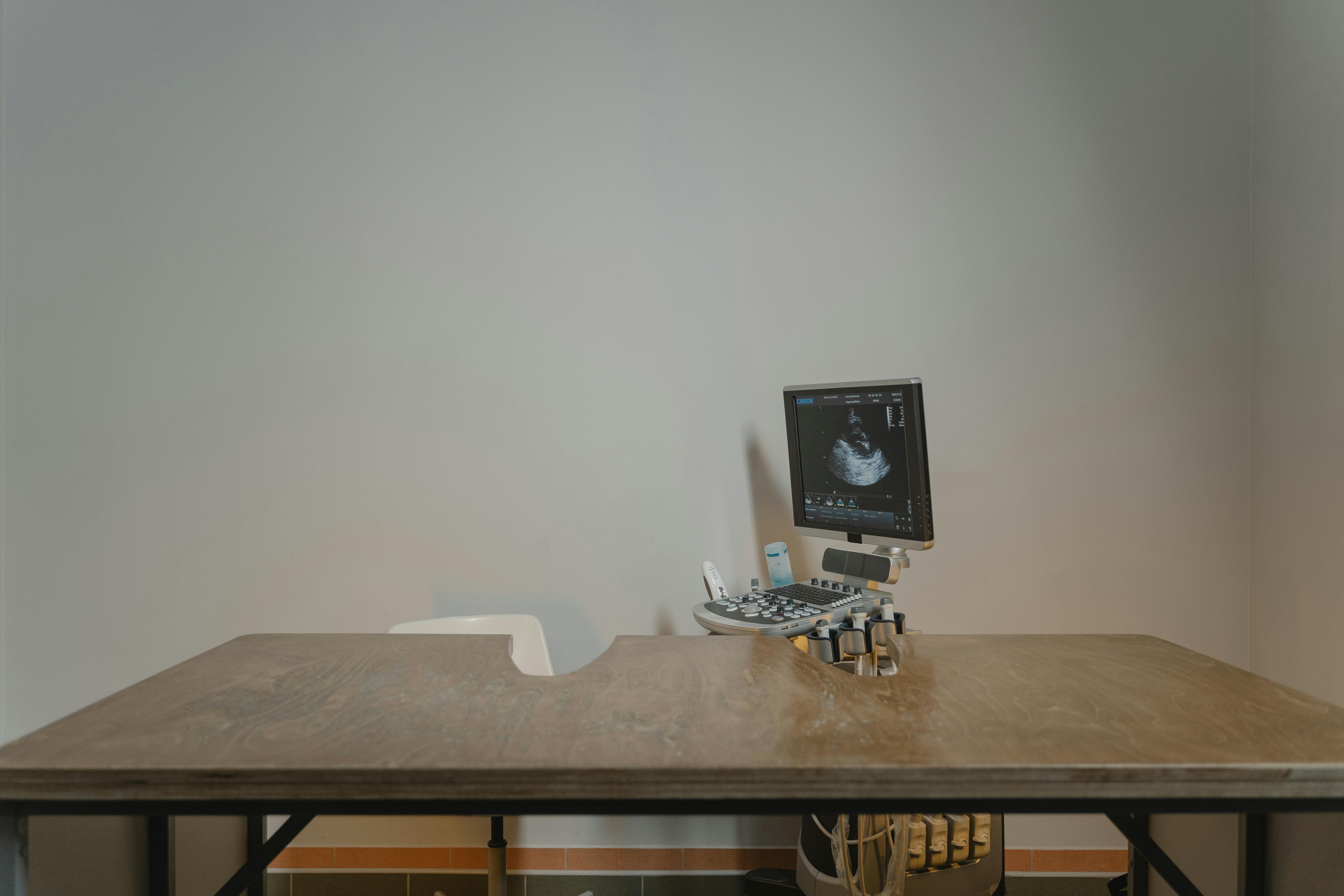
Why Console Navigation That Gets Worse With Use Often Exposes Panel-Control Weakness Earlier Than A Hard Failure
Console navigation worsening with use? Learn to diagnose panel control board failure and make the right procurement decision—before someone suggests replacing the whole system.
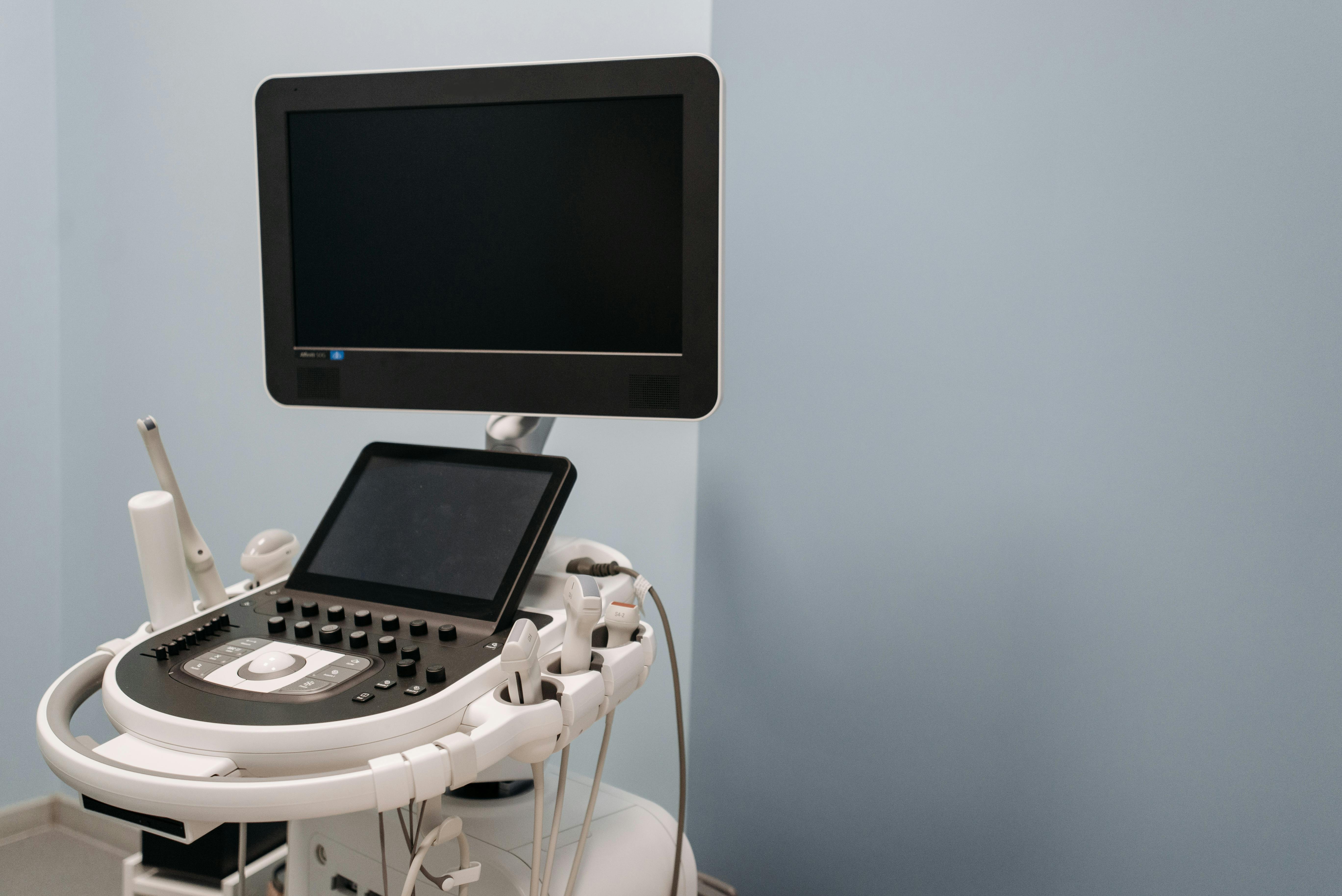
Why A Drifting Keyboard Cluster Usually Points To The Shared Input Path, Not Five Bad Keys
Keyboard keys failing in groups point to a shared input path problem, not bad switches. Learn when a keyboard assembly purchase beats chasing individual keycaps.

Why Clustered Console Hesitation Usually Signals a Shared Input Path Weakness Before Any Key Fully Dies
Clustered hesitation signals shared input path weakness before keys die. Buying during the hesitation window saves 30–60% over emergency replacement.